CONTENTS
1.2 Purpose of the Safety Management Plan
1.3 Structure of the Safety Management Plan
2....... Safety Management System
2.1.1 Health and Safety Policy
2.1.2 Specific Policy in Compliance with the Gas Safety Regulations
2.7 Accident / Incident Investigation
2.10 Accident Control and Hazard Elimination
3....... Key Safety Design Features
3.2 Using, Purging and Flaring
3.3 Access Control and Work Control in a Natural Gas Controlled Area
3.7 Overpressure and Blowdown System
3.8 Subsea Pipeline Protection
4....... Operation and Maintenance (O&M) Procedures
4.5 Isolating the LPS Pipeline
5....... Emergency Response Procedures
5.1 General Emergency Response Strategy
6....... Marine Safety Arrangement and Procedures
7....... Regular Safety Review and Audit
List of Tables
Table 2.1 Inspection Frequency for Subsea Natural Gas (NG) Pipeline
Table 4.1 Roles and Responsibilities of the O&M Team
List of Figures
Figure 1.1 Indicative Location of Key Project Components
Figure 2.1 H&S Organisational Structure
Figure 2.2 H&S Organisation Chart for the Generation Division
Figure 2.3 Evacuation Muster Points on LPS
Annex
Annex A HKE’s Safety and Health Policy
1.
Introduction
1.1
Background
To support the increased use of natural gas in Hong Kong from 2020 onwards, Castle Peak Power Company Limited (CAPCO) and The Hongkong Electric Co., Ltd. (HK Electric) have identified that the development of an offshore liquefied natural gas (LNG) receiving terminal in Hong Kong using Floating Storage and Regasification Unit (FSRU) technology (‘the Hong Kong Offshore LNG Terminal Project’) presents a viable additional gas supply option that will provide energy security through access to competitive gas supplies from world markets. The Project will involve the construction and operation of an offshore LNG import facility to be located in the southern waters of Hong Kong, a double berth jetty, and subsea pipelines that connect to the gas receiving stations (GRS) at the Black Point Power Station (BPPS) and the Lamma Power Station (LPS). The location plan is shown in Figure 1.1.
The Environmental Impact Assessment (EIA) Report for the Project was submitted to the Environmental Protection Department (EPD) of the Hong Kong Special Administrative Region Government in May 2018. The EIA Report (EIAO Register No. AEIAR-218/2018) was approved by EPD and the associated Environmental Permit (EP) (EP-558/2018) was issued in October 2018. An application for Further Environmental Permits (FEP) was made on 24 December 2019 to demarcate the works between the different parties. The following FEPs were issued on 17 January 2020 and the EP under EP-558/2018 was surrendered on 5 March 2020:
§ the double berth jetty at LNG Terminal under the Hong Kong LNG Terminal Limited, joint venture between CAPCO and HK Electric (FEP-01/558/2018/A) ([1]);
§ the subsea gas pipeline for the BPPS and the associated GRS in the BPPS under CAPCO (FEP-03/558/2018/B) ([2]); and
§ the subsea gas pipeline for the LPS and the associated GRS in the LPS under HK Electric (FEP-02/558/2018/A) ([3]).
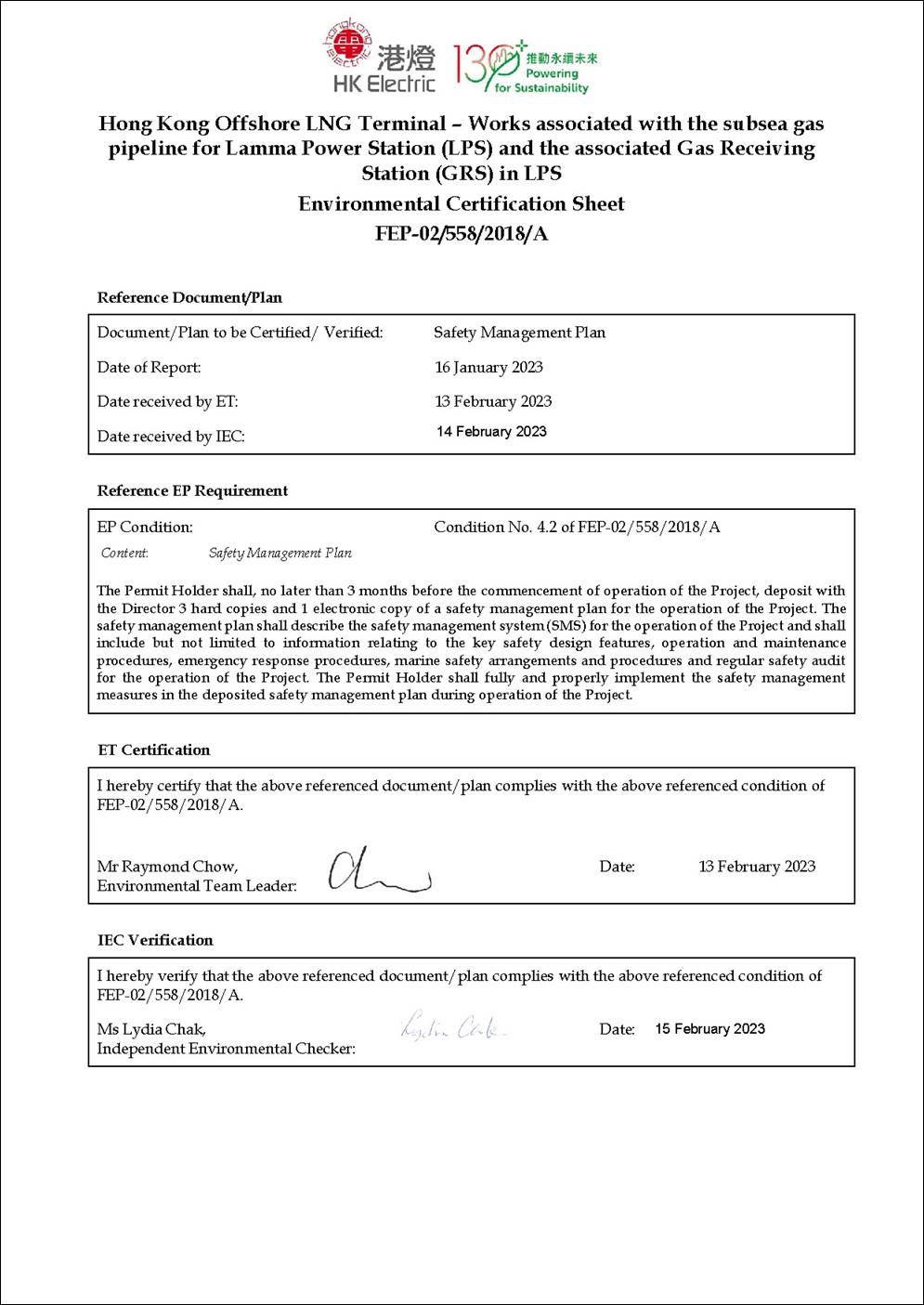
In accordance with Condition 4.2 of the FEP of the subsea gas pipeline for the LPS and the associated GRS in the LPS (FEP-02/558/2018/A) (‘the Project’):
|
FEP No. FEP-02/558/2018/A, Condition 4.2: “The Permit Holder shall, no later than 3 months before the commencement of operation of the Project, deposit with the Director 3 hard copies and 1 electronic copy of a safety management plan for the operation of the Project. The safety management plan shall describe the safety management system (SMS) for the operation of the Project and shall include but not limited to information relating to the key safety design features, operation and maintenance procedures, emergency response procedures, marine safety arrangements and procedures and regular safety audit for the operation of the Project. The Permit Holder shall fully and properly implement the safety management measures in the deposited safety management plan during operation of the Project.” |
1.2
Purpose
of the Safety Management Plan
As stated in Condition 4.2 of the FEP, this Safety Management Plan presents the safety management system (SMS) for the operation of the Project, including information relating to the key safety design features, operation and maintenance procedures, emergency response procedures, marine safety arrangements and procedures and regular safety audit for the operation of the Project.
This Safety Management Plan covers the facilities of the LPS Pipeline connecting from the LNG Terminal Jetty (not including the Jetty itself) up to and inclusive of the GRS in the LPS.
1.3
Structure
of the Safety Management Plan
The remainder of this Safety Management Plan is set out as follows:
§ Section 2 presents the safety management system for the operation of the Project;
§ Section 3 describes the key safety design features of the Project;
§ Section 4 details the operation and maintenance (O&M) procedures of the Project;
§ Section 5 presents the emergency response procedures;
§ Section 6 presents the marine safety arrangement and procedures; and
§ Section 7 presents the mechanism for regular
safety review and audit.
2.
Safety Management System
The safety management system described in the following sections refers to the various Administration Standing Instructions (ASI), Health & Safety Standing Instructions (HSI), Safety Code of Practice (SCOP), as well as the Generation Division of HK Electric Occupational Health & Safety Manual currently in effect for the commissioning, operation, and maintenance activities relevant to the facilities at LPS and the LPS Pipeline. The Generation Division is responsible for ensuring the natural gas plant of LPS and the LPS Pipeline are operated and maintained in such a manner that all legislative requirements are complied with, and to a high standard such that availability, reliability and efficiency are maximized in a cost effective manner.
2.1
Safety
Policy
2.1.1
Health
and Safety Policy
The Health and Safety Policy of the Hongkong Electric Co., Ltd. (HK Electric, or Company) is issued by the Managing Director and is posted on the Company Portal. It sets out the direction of the Company with respect to occupational health and safety. The Health and Safety Policy is made known to every employee of the Company and is available to all stakeholders outside the Company.
The Company is committed to protecting the health and safety of employees, customers, contractors and the public by conducting business in a safe and socially responsible manner. The Company will comply fully with all applicable laws and regulations and strive to integrate health and safety considerations into all aspects of business activities.
The policy is reviewed once every two years, or whenever necessary, by a committee chaired by the Secretary of Health & Safety Board.
The Health and Safety Policy is provided in Annex A.
2.1.2
Specific
Policy in Compliance with the Gas Safety Regulations
The Company complies with The Gas Safety (Registration of Gas Supply Companies) Regulations which stipulates that it shall be the duty of a registered gas supply company:
§ to ensure, in carrying out its business as a gas supply company, so far as is reasonably practicable, the health and safety of its employees and to carry out its gas operations in a safe manner so that members of the public are not subjected to undue risks from gas; and
§ to prepare and maintain a written statement of its general policy with respect to the health and safety at work of its employees and the organization and arrangements for the time being in force for carrying out that policy.
The Major Gas Accident Prevention Policy is posted on the Company Portal and is produced to satisfy the statutory requirements of the Gas Safety (Registration of Gas Supply Companies) Regulations. It clearly states the commitment of both Projects and Generation Divisions of the Company to develop, implement and maintain a management system for controlling occupational health & safety (OH&S) risks arising from the use of natural gas as a fuel in the aspects of design, erection, operation and maintenance of natural gas facilities at LPS and the LPS Pipeline, with an ultimate goal in prevention of a major gas accident. A “Natural Gas Safety Manual” is developed detailing the procedures for documenting, implementing and maintaining the policy.
2.2
Organisational
Structure
The Health and Safety Board (H&SB) ensures that HK Electric’s Health and Safety Policy Statement is fully and properly implemented, and oversees all matters of health and safety concerning the Company’s operations, including the facilities at LPS and the LPS Pipeline. The H&SB is the highest authority in steering OH&S matters in the Company. It is chaired by the Managing Director. General Manager (Generation) [GM(G)] represents Generation Division in the H&SB. The Generation Division Health and Safety Committee is the highest authority for managing OH&S in Generation Division.
At the divisions/department levels, the Generation Division, Projects Division and Transmission and Distribution Division have established a Divisional Health & Safety Committee within its division and where appropriate a Departmental Health & Safety Committee within its department. Each of these divisions have at least one safety unit as an executive branch of the committees. The H&S organisational structure and the H&S organisation chart for the Generation Division are presented in Figure 2.1 and Figure 2.2, respectively.
2.3
Safety
Training
Persons performing natural gas work in relation to the design, construction, maintenance, operation and emergency handling are required to have a specific level of competency. Training plan, including refresher training requirements, is established that is applicable to general employees, visitors and contractors for entering or working in Natural Gas Controlled Area.
HK Electric provides different levels of natural gas training courses for its employees, contractors and visitors. Scope and training contents of the courses are designed to satisfy the needs of the target groups of participants.
There are 5 different levels of gas training:
§ Level 1: General Information Training;
§ Level 2: Site Induction Training;
§ Level 3: Natural Gas Safety Training for Gas Workers;
§ Level 4: Natural Gas Safety Training for Competent and Authorised Persons; and
§ Level 5: Natural Gas Safety Training for Engineers and Senior Staff.
Only those who possess the minimum level of competency are allowed to perform the appropriate work related to natural gas. All the safety training records will be kept properly.
2.4
In-house
Safety Rules
HK Electric Safety Rules set out the rules relating to all aspects of work concerning with the operation of the Company’s system or apparatus. Personal copies of the Safety Rules are issued to all Authorised and Competent Persons of HK Electric and contractors engaged in these activities. HK Electric Safety Rules are divided into two parts - electrical and mechanical and have included appropriate rules related to natural gas safety.
Close supervision of natural gas activities is implemented to ensure workers comply with the Safety Rules for natural gas. The operation of the Company’s generation, transmission and distribution system is governed by two sets of rules, namely Safety Rules (Electrical) and Safety Rules (Mechanical). All persons who may have to work on or be concerned with the operations of the Company’s system or apparatus or mechanical plant must make themselves thoroughly conversant and comply with both the relevant statutory requirements and these Safety Rules. Ignorance of the statutory requirements or Safety Rules will not be accepted as an excuse for negligence of duty.
The System Operating Procedures set out the duties and routine procedures to be carried out by those who are directly concerned with the coordinated operations of the generation, transmission and distributions systems. Administration of the Safety Rules and System Operating Procedures is described in the Corporate Health and Safety Manual.
Supervisors are responsible for clearly explaining the relevant rules and instructions to their subordinates.
Supervisors are responsible for ensuring their subordinates comply with the rules and instructions. Compliance with rules and instructions should be recognized positively and considered in employee appraisals. Violation of rules and instructions will be handled according to the Corporate Disciplinary Procedures.
2.5
Inspection
Programme
Health and safety inspection is an active monitoring programme to measure and monitor the health and safety performance against predetermined plans and standards.
Procedures are in place for conducting regular workplace safety inspections to ensure that safety standards and safe means of access and egress are properly maintained and these are monitored through the Health and Safety Committees and Sub-committee(s).
Weekly surveillance of the Gas Receiving Station is performed according to the following checklist:
§ Look for any sign of leakage or malfunction, abnormal vibration or noise;
§ Check the integrity of the fencing and entry gates, and check that all appropriate warning signs are in place and readable;
§ Check the above ground and non-insulated pipework of any corrosion or damage; and
§ Check the condition of local instruments and observe whether they are indicating normal function.
Regular monthly inspection shall be carried out on all the pipework and equipment using portable gas detection equipment to check all mechanical joints and threaded fittings that are accessible.
A summary of the various means of inspection and monitoring of subsea pipeline conditions is provided in Table 2.1. All the inspections shall be conducted by competent person from HK Electric or appointed by HK Electric.
Table 2.1 Inspection Frequency for Subsea Natural Gas (NG) Pipeline
|
Inspection |
Frequency |
Purpose |
|
Pipeline leak detection system |
Continuous on-line |
Monitor and identify location of leakage along the pipeline. |
|
Measurement of natural gas composition |
Continuous on-line |
Monitor whether the pipeline internal is subject to attack by corrosive components. |
|
Patrolling |
Every two (2) months. |
Ensure there are no anomalies observed on the sea which may cause damage to the pipeline. |
|
Measurement of cathodic protection system |
Once every three (3) months at Lamma Extension. |
Ensure pipeline external is receiving protection from sacrificial anodes, and monitor condition of the insulation joints. |
|
Analysis of debris collected from gas filters |
Every year |
Monitor condition of the natural gas subsea pipeline. |
|
Ground settlement at Gas Receiving Station and along the pipeline on Lamma land side |
Every three (3) months |
Determine whether integrity of pipeline on the land side is affected. |
|
Analysis of debris collected from valve’s internal |
Defect basis, and whenever there is such opportunity |
Monitor condition of the natural gas subsea pipeline. |
|
Analysis of debris collected from onshore pipeline header |
Every three (3) years |
Monitor condition of the natural gas subsea pipeline. |
|
External inspection |
Every five (5) years after installation of the pipeline. |
Confirm the integrity of the pipeline protection; Measure the burial depths and the locations of the pipeline where rock armour had not been placed; Measure the changes in seabed levels within the survey corridor along the pipeline route, since it was installed; and Identify obstructions; third party installed facilities and hazards, if any, within the survey corridor along the pipeline route. |
|
Pipeline location |
Approximately ten (10) years from pipeline installation, or immediately following any significant geotechnical event, e.g. earthquake or volcanic activity. |
Determine whether pipeline integrity is affected. |
|
Pipeline defect identification |
At an interval of ten (10) years beginning from first inspection, or after any significant geotechnical event, e.g. earthquake, seabed scour or movement which might affect the rock-dumped zones. |
Determine whether pipeline integrity is affected. |
|
Pipeline wall thickness |
At an interval of ten (10) years beginning from first inspection, or within two (2) years following any significant process upset condition, e.g. liquid in pipeline. |
Determine whether pipeline integrity is affected. |
The results of the inspections are brought to the attention of senior management or relevant health and safety committee, where appropriate. Inspection results are evaluated and remedial actions are formulated if necessary. Should there be any corrective action, they should be implemented as quickly as reasonably practicable.
2.6
Hazard
Control Programme
Methane, the primary component of NG, is colourless, odourless, and tasteless, and is classified as a simple asphyxiant for human exposure. Because it is odourless, NG is not easy to detect.
At a 4 % concentration of gas in air, NG is at the Lower Flammability Limit (LFL). Below this gas/air ratio, the cloud is too dilute for ignition. At a 15 % concentration of gas in air, NG is at its Upper Flammability Limit (UFL). Above this gas/air ratio, the cloud is too rich to ignite.
When a gas leak occurs, the downwind distance that flammable gas might reach depends on the volume of NG leaked, the rate of the spill, and the prevailing weather conditions. NG will not normally travel far before it disperses. However, if it reaches an ignition source before it has sufficiently dispersed, a gas fire may result.
When gas is released into an enclosure it will cause asphyxiation within the enclosure. When NG is ignited, it can produce a jet fire or flash fire. NG can also explode if ignited within a confined space such as a building or structure. Gas leak or broken gas line and similar situations may range from minor to potentially major incidents. They should be attended to as potentially dangerous situations. Operations (OPS) staff shall be responsible for locating and eliminating leak sources. Duty Assistant Fire & Security Supervisor (AFSS) shall take necessary actions to provide for life and property safety.
The goal of the process hazard control programme of Generation Division is to identify and to control risks to health and safety arising from various processes in its operation. A systematic approach for implementation of the process hazard control programme has been adopted.
The following summarises the major components of the process hazard control programme:
§ Process safety information;
§ Risk management procedure;
o Process to be analysed for risk management
o Hazard identification and selection of methodology
o Job Safety Analysis and Pre-job risk assessment
§ Operating procedures;
§ Training and competency of employees;
§ Mechanical integrity programme; and
§ Monitor and review.
Personal Protective Equipment (PPE) is for the Company’s activities in which the potential for personal injury could exist. In general, risk assessment should be conducted before any operation, maintenance or other activities to identify suitable PPE for the work to be carried out. In addition, Divisions/Departments are recommended to maintain a list of assets or a list of work processes such that risk assessments could be conducted with an asset-based or process-based approach.
All necessary items of PPE are issued to employees who should sign a receipt for the equipment.
PPE is not a substitute for any method of fixed protection that could be implemented. Engineering controls and safe systems of work should always be considered first and PPE should always be regarded as the last resort.
Division/Department Heads should train and instruct their employees on when they need to wear PPE and the correct method of wearing PPE. These include but are not limited to the following:
§ Safety helmets;
§ Eye and face protection;
§ Safety footwear/shoes;
§ Protective clothing;
§ Respiratory equipment;
§ Ear protectors;
§ Safety harnesses; and
§ Gloves and other hand protection aids.
2.7
Accident
/ Incident Investigation
The accident and major incident reporting and investigation system for the facilities at LPS and the LPS Pipeline is supervised by the Health and Safety Board. Natural gas accident and major incident reporting and investigation are conducted in a systematic manner. The approach includes:
§ Reporting of the accident and major incident information including:
o General circumstances (location, date, time, persons and facilities involved).
o Cause and likelihood of recurrence.
o Consequence and severity.
o Potential worst case severity, if further safeguard had failed or events had been slightly worse.
§ Investigation, which will determine:
o Basic and underlying causes.
o Immediate measures to be taken to prevent recurrence.
o Longer term preventive measures, including management control improvement identification.
o Corrective action follow-up and review of implemented changes.
§ Accident and major incident data analysis:
o Assessment of data to identify frequently occurring: assess data related to high frequency, high consequence, high potential consequence or high risk accidents or incidents to determine preventive measures.
o Assessment of effectiveness of preventive measures.
All station employees and contractors shall report any accident involving natural gas or any incident potentially involving natural gas. In the case where an emergency/incident occurs during commissioning of the gas facilities, Generation Division must take charge of the emergency/incident as soon as it is reported by the person discovering the emergency.
Major Gas Emergency means any gas emergency which is an accident following the definition state in Section 2 under the Gas Safety (Registration of Gas Supply Companies) Regulations (Cap. 51 sub. Leg. E). As a major gas emergency is considered as a “crisis” under the Company's Crisis Management Plan (CMP), procedures spelt out in the CMP shall be followed.
Reportable Gas Incident means:
§ Reporters of news media present at the scene of gas incident;
§ Gas Incident relating to liquefied petroleum gas/natural gas facilities reported to “999” to summon emergency services from Fire Services Department (FSD), Police and/or the Ambulance; or
§ Gas Incident which may attract media attention or stimulate public grievance.
Where there is a reportable gas incident, the registered gas supply company shall report the incident by telephone to Gas Authority not later than 2 hours after knowing its occurrence. The report should provide the Authority with brief information on the incident such as location, time of incident and any casualty involved, whether there is a fire and/or explosion, or only gas leakage.
If a Major Gas Emergency or a reportable gas incident has occurred during commissioning, then representatives from Projects Division, Generation Division and the Contractor (if involved) should take part in the investigation following the established protocol.
It is important that the actual scene of the Major Gas Emergency or the reportable gas incident shall be inspected as soon as possible after the occurrence of such emergency or incident is reported. The duty Senior Operations Engineer, or his deputy, will start the preliminary investigation and, subject to it being safe to do so, inspect the scene.
The report of the investigation should be submitted to the Secretary of the Health and Safety Board, Head of System Operations (HSO) within 14 days.
Not later than 28 days after the day on which the emergency/reportable gas incident occurred, the final copy of the report must be submitted to the Gas Authority.
2.8
Emergency Preparedness
When circumstances arise that threaten the safety of Company personnel and property, immediate action must be taken to minimise the risk. A Site Emergency will be declared as necessary by the General Manager (Generation) [GM(G)] or in his absence by his representative at site.
When the station emergency alarm is sounded:
§ All operating personnel will muster for further instructions in their respective Control Room; and
§ All other personnel inside the station buildings, including visitors and contractors, will proceed to the recommended evacuation muster point(s) and report to their direct supervisor or, for visitors, the HK Electric employee looking after them, when they reach a muster point.
There are three evacuation muster points for LPS:
§ Near the guard post at Passenger Jetty;
§ Near the guard post at East Gate; and
§ Lamma Extension East Heavy Unloading Area (junction of Intake Road and Middle Road).
In deciding where to evacuate to, personnel must be mindful of the prevailing circumstance at the time e.g. wind direction in the case of a gas emergency, and pay attention to any broadcast information available. Personnel will remain at the selected location until the order is given either to return to their normal working place or to leave site.
Emergency drills based on reasonably foreseeable accident scenarios are carried out to provide training, test the emergency plan and feedback lessons learnt in order to improve the emergency plan. Following are the four major gas emergency scenarios:
§ Serious natural gas leak;
§ Major fire;
§ Explosion; and
§ Major leak of sub-sea natural gas pipe.
Each of the above scenarios will be included in the drill schedule at least once every three years.
Fire evacuation drills are also conducted in all major buildings at LPS on a quarterly basis. Members of each of the four shifts will be exposed to one evacuation drill at least once a year.
The Senior Manager (Loss Prevention & Training) [SM(LP&T)] will be responsible for arranging these drills.
2.9
Contractors’
Management
It is stated in the Company’s Health & Safety Policy that all Contractors shall meet the same occupational health and safety standards and requirements as the Company. Every contractor must take all necessary measures to safeguard the health and safety of their employees and persons, including the public at large.
Only those contractors who can demonstrate ability and commitment to ensure health and safety at work shall be included in the Recognised Tenderer and Bidder Register, and awarded contracts.
2.10
Accident Control and Hazard Elimination
Natural gas risk management shall be conducted in accordance with the Major Gas Accident Prevention Policy. The risk management system comprises of:
§ Management of the risks associated with the ongoing operation and maintenance of the existing facilities.
§ Management of the risks which may arise from any changes to the existing facilities.
§ Audit, action item follow-up, training and competence systems.
The risk management process includes all factors related to an activity involving potential hazards, to make a judgment about the associated risks and implement appropriate controls.
Natural gas risk management is conducted when
there are changes or development of new projects within the LPS facilities and
the LPS Pipeline. Before the introduction of new
substances/materials/work process/plant which may constitute hazards to
employees, the Division/Department Head initiating the change shall, where
necessary, carry out the following steps:
§ the identification of possible risks, if any, associated with the newly introduced substance/material/work process/plant;
§ the assessment of risks associated with that newly introduced substance/material/work process/plant at the workplace. The assessment procedure shall be defined by the Division/Department Head initiating the change or his/her specifically designated deputy;
§ deciding what control measures can be taken;
§ advising concerned employees of potential risks;
§ the implementation programme of health surveillance where necessary;
§ consultation with the Health and Safety Sub-Committee members in the workplace on all proposed changes to the workplace including those changes which may affect health and safety at the workplace;
§ provision of such information, instruction, training and supervision as will enable all employees to perform work safely; and
§ provision of personal protective equipment where it is not practicable to control hazards by other means.
Existing substances/materials/work process/plant shall be regularly reviewed by Generation Division/ Department Head or his/her specifically designated deputy whenever it is known that there is a likelihood of hazard.
3.
Key Safety Design Features
3.1
Earthing
System
Earthing connections are provided in Natural Gas Pipelines and Natural Gas Plant for lightning protection and for discharging static electricity. If work is to be carried out on a Natural Gas Pipeline or Natural Gas Plant, special provision must be made to ensure that continuity of earthing of the pipeline and plant charged with natural gas is not affected.
3.2
Using,
Purging and Flaring
Preventing the mixing of natural gas and air is normally achieved by purging the contents of the pipe-work concerned using an inert gas, either to totally displace one before introduction of the other, or as a substantial buffer between them to prevent mixing of natural gas and air during the purging process.
Instruction has been established for using, purging and flaring natural gas contained in the subsea pipelines, plant and equipment. It covers work within the on-shore natural gas system that involves purging from natural gas, to air or from air to natural gas, associated with the commissioning/putting into service and decommissioning/isolation of on-shore pipelines, equipment and pipe-work.
3.3
Access Control and Work Control in a Natural Gas
Controlled Area
A Natural Gas Controlled Area (NGCA) is defined as an area in which special precautions must be taken as natural gas may be present. To ensure the safety of plant and personnel, control of access to NGCA is necessary. Different systems are being used for access control to the NGCAs. For Gas Receiving Station (GRS), wire fencing with CCTV + Access Card System are used.
If work is to be carried out in a Natural Gas Controlled Area (NGCA), on or near a Natural Gas (NG) Pipeline (above sea level) or NG Plant, special provision must be made to ensure that the safety of personnel, NG Pipeline and NG Plant are not affected.
To ensure the safety of personnel on subsea pipeline inspection, various in-house documents were developed and implemented to provide practical guidance for visitors, employees and contractors to comply with the requirements on (i) NGCA access control, (ii) special provision for works to be carried out in a NGCA, (iii) operation steps & safety precautions in GRS, and (iv) means and precautions for routine Patrolling Inspection, etc.
3.4
Fire Protection
Systems
All critical areas of the LPS are protected by either water based or gas type fire extinguishing systems which automatically raise an alarm when the systems operate. Where active fire protection systems are not suitable, automatic fire alarm systems (AFA) are employed to provide passive fire protection. AFA includes the following detection systems:
§ Passive Smoke Detection System;
§ Active Smoke Detection System;
§ Point Heat Detection System;
§ Linear Heat Detection System;
§ Infra-red Detection System;
§ Ultra-violet Detection System; and
§ Optical Beam Smoke Detection System (LMX Maintenance Building).
In addition, the following systems are provided to address fire safety.
§ Manual fire alarms installed at strategic locations;
§ Fire computers for continuous monitoring;
§ Fire-fighting water supply system;
§ Portable fire-fighting equipment;
§ Water-based extinguishing systems; and
§ Gas extinguishing system.
To detect events of fire and flammable gas leakage, portable gas detectors are provided in means of sampling the atmosphere around gas pipelines and equipment and measuring the seriousness of the leakage. Fixed gas detectors continuously monitor the natural gas pipework inside the unit turbine enclosures and the fuel gas control system. A regular check by every shift is made for any outstanding gas detection alarms.
3.5
Process
Control System
Process control valves (e.g. pressure control, temperature control etc.) are provided in the GRS area in order to continuously maintain the stability of the overall process operation. Process deviation alarms are also provided to alert the operators to take necessary actions.
3.6
Emergency
Shutdown System
Emergency Shutdown (ESD) system is provided at the GRS area in the event of an emergency which allows the system to return to a safe, static condition so that any remedial action can be taken. The ESD system can be activated automatically through various process initiators and manually through push buttons.
ESD valves are provided in the GRS in order to isolate the inventory in the event of an emergency situation so that the leakage of hazardous materials can be controlled and minimized.
3.7
Overpressure
and Blowdown System
Various pressure safety valves are provided and designed to vent automatically to the vent header and eventually to be flared in stack to prevent overpressure.
3.8
Subsea
Pipeline Protection
Segments of the LPS pipeline is designed with pipeline protection against anchor drop and anchor drag including armour rock protection based on the risk of anchor damage from the marine traffic traversing across or along the pipeline route.
4.
Operation and Maintenance
(O&M) Procedures
4.1
O&M
Strategy
The LPS facilities and the LPS Pipeline will be operated and maintained by LPS O&M team with corresponding O&M strategy.
Comprehensive operating procedures have been prepared for associated control systems, the high-pressure gas pipelines, pig receiving facilities and the gas receiving station. These procedures provide guidance on all aspects of operating the facilities under normal conditions, during maintenance and in emergency situations, also covering normal start-up and shutdown of the facilities, emergency shutdown and inspection.
The operational control covers the following scopes but not limited to:
§ Adopt permit-to-work system;
§ Control of OH&S risks using work instructions & risk assessment results;
§ Develop process hazard control & occupational health assurance programmes
§ Develop operational manual for high risk activities (e.g. hot work and sparking, working in confined spaces, lifting operations, and etc.)
Maintenance procedures have also been prepared for associated control systems, pipelines and other facilities. HK Electric manages the maintenance of all existing systems and facilities at the power station using its Computerized Stores and Maintenance System. The system covers all aspects of maintenance of the natural gas facilities.
A Mechanical Integrity Programme is also adopted to ensure the continued integrity of process plants and equipment. The elements of the Mechanical Integrity Programme include the identification and categorisation of plants, equipment and instruments, inspections and tests, testing and inspection frequencies, development of maintenance procedures, training of maintenance personnel, establishment of criteria for acceptable test results, documentation of test and inspection results, and documentation of the manufacturer’s specified mean-time-to-failure data.
All operating and maintenance procedures are reviewed annually as part of the scope of the audit of the risk and safety management system (See Section 7 below) to ensure that they are effective and in accordance with current legislative requirements.
Inspection/checks/supervision of natural gas activities are implemented to ensure workers comply with the operation and maintenance instructions and to ensure work quality.
In addition, HK Electric Safety Rules set out the rules relating to all aspects of work including the O&M aspect. The supervision of O&M activities is also implemented to ensure the compliance with the in-house Safety Rules for LPS facilities.
4.2
O&M
Team Structure
The O&M management team supports the design and management of the LPS facilities.
The roles and responsibilities of the O&M team are shown as below:
Table 4.1 Roles and Responsibilities of the O&M Team
|
Roles |
Responsibilities |
|
Department/Division Heads or Above |
§ Set policy criteria and objectives, approve and authorise new top-tier policy documents, procedures and codes; § Responsible for ensuring the facilities are designed, constructed, installed, operated and maintained safely and effectively and that the health and safety of employees and the public are safeguarded. |
|
Chief Engineers/Senior Engineers/Section Heads |
§ Support the Department/Division Heads in the operation and maintenance of the facilities; § Responsible for the proper design, construction and installation or the safety and effective operation and maintenance of a particular part of the facilities; § Supervise subordinates to ensure that high standards are maintained; § Support the Department/Division Heads in promoting new policy initiatives, codes and standards, etc., and are accountable to them. |
|
Supervisors and Technicians |
§ Carry out duties under the supervision of Senior Engineers/Section Heads. |
4.3
Operation
Personnel
Authorized Persons are operation personnel appointed by HK Electric for the operation of the LPS facilities and the LPS Pipeline.
Authorized Persons shall communicate through dedicated communication channels on matters arising in the daily operation of the LPS Pipeline. They are also responsible for emergency operation and planned outage of the LPS Pipeline.
4.4
Communication
Dedicated voice and data communication between the LNG terminal and LPS shall be established as a main communication channel. The communication hardware can comprise of remote terminal unit (RTU), Data Logger and Direct Line Telephone installed at the LNG Terminal and LPS. Communication interfaces of the HK Electric system are installed in two locations: the Gas Receiving Station and Central Control Room No. 2 (CCR2) at the LPS. Direct line telephone and data logger are provided for different applications.
Routine testing of the main and backup communication systems shall be carried out monthly. Chinese or English can be used for verbal and written communication.
4.5
Isolating
the LPS Pipeline
Works to be carried out on this pipeline or on the termination point of HK Electric’s Lamma Power Station would require isolation of the supply point installed at the LNG Terminal.
Alternatively, works to be carried out on the supply point at the LNG Terminal would require isolation of the termination point located at HK Electric side by an Authorized Person. For works to be carried out at both sides of the LPS Pipeline, both parties shall discuss and agree on the isolation points.
The isolation must be achieved with double block and bleed using either:
§ A single double faced valve, with the valve body vented between the two faces;
§ Two valves with the space between them vented.
If necessary, more positive isolation can then be achieved by:
§ Removal of sections of pipe-work and fitting blank flanges to flanges on the live sides; or
§ Insertion of spades between flanges on either side of the decommissioned plant.
In every case there must be a means of venting the space between the valve(s) controlling the gas and the spade or blank flange. For spades the type of material and plate thickness must be adequate for the maximum anticipated pressure. Blank flanges must be of equivalent rating to the flange to which it is mated. Jointing materials and methods must be appropriate to the maximum pressure rating of the system.
If pressure testing is to be conducted on the LPS Pipeline, special precautions shall be taken and agreed between both parties.
4.6
Change
Management
Risk, particularly major gas risks, arising due to changes in facilities or process will be managed in accordance with the established change management procedure, covering onshore GRS and the LPS Pipeline
The established change management procedure addresses the following :
§ General change
o For a general change that does not constitute a change as defined as the following categories, the HKE risk identification, assessment and control process shall be followed;
§ Change under Environmental Impact Assessment Ordinance
o Following the Environmental Impact Assessment Process Technical Memorandum, it is normally experienced that the Environmental Protection Department issue a study brief specifying the scope of the Hazard Assessment study (i.e. Hazard to Life Assessment) and essentially is a Quantitative Risk Assessment (QRA).
§ Change under Gas Safety Ordinance
o An engineering change to a Notifiable Gas Installation is proposed, risk assessment submissions including
§ Hazard and Operability (HAZOP) study of new facilities;
§ QRA comparing new to old risk, showing no net increase in risk with risk control measures and;
§ Safety Case for new facilities with relevant information from above HAZOP and QRA after commencing operations.
o A change to the scope of the gas business in terms of the Registered Gas Supply Company status may involve an exchange of letters. Change in the management of the business that could impact on safety should be pursued through the Registered Gas Supply Company process for any Notifiable Gas Installation that the new gas business creates.
§ Change under Hong Kong Planning Standards and Guidelines Chapter 12, Potentially Hazardous Installations
o It is proposed to store quantities of dangerous goods on any HKE site in excess of the thresholds set by the Authority, then a Hazard Assessment (essentially a QRA study) is required to be prepared and submitted to Electrical and Mechanical Services Department.
All modifications should normally be done according to the procedure unless otherwise approved by the General Manager (Generation) [GM(G)]. No modification, however small, should be carried out on any equipment without first informing the user department and receiving their approval.
The risk(s) associated with personal safety, plant
safety and asset management activities due to a modification shall be
thoroughly considered before a supervisor approves it. The Chief Technical
Services Engineer (CTSE) will ensure that each modification has been discussed
in relevant meeting(s) or where appropriate, a risk assessment be conducted
before its implementation.
5.
Emergency Response Procedures
Emergency response procedures have been established with reference to the Major Gas Emergency Plan developed by HK Electric.
The Major Gas Emergency Plan includes:
§ Emergency Command Structure.
§ HK Electric’s Point of Contact with Government regarding Preparation of Off-site Emergency Plan.
§ Emergency Scenarios, including:
o Types of Foreseeable Accidents.
o Intended Strategy for Dealing with Each Accident.
o Emergency Response Personnel, Roles and Responsibilities.
o Emergency Response Equipment, Protective and Rescue Systems.
o Station Fire Team.
o Availability and Function of Other Resources.
§ Arrangements for Limiting the Risks to Persons Onsite or near the Pipeline.
§ Off-site Emergencies.
§ Training and Drills.
§ Arrangements for Co-ordination with Off-site Agencies.
5.1
General Emergency Response Strategy
The intended emergency response strategy for on-site foreseeable accidents at Lamma Power Station is as follows:
§ Raise alarm.
§ Evacuate people.
§ Isolate.
§ Summon assistance if necessary.
§ If there is a gas leak (not yet ignited):
o Eliminate ignition sources by using/venting/flaring pipeline inventory.
§ If there is a fire:
o Apply cooling (water) to vulnerable process items and structures.
o Carefully consider whether it is appropriate to extinguish the gas fire. Generally gas fires should not be extinguished as it is preferable for them to burn as jets rather than risk an explosion.
§ Make area safe.
§ Only when all clear is declared, allow people back into the area and recommence work.
§ Initiate clean up and recovery.
The intended emergency response strategy for sub-sea pipeline gas leak and fire on sea are as follows:
§ Raise alarm (notify Gas Authority, Marine Department, FSD, LNG Terminal, etc.).
§ Seek Marine Department assistance in evacuating and excluding shipping from area at risk.
§ Consider requesting LNG Terminal to isolate pipeline.
§ Consider using/venting pipeline inventory.
§ Summon assistance if necessary.
§ Only when all clear is declared, allow shipping back into the area and recommence gas transmission.
§ Initiate clean up and recovery (repair to pipeline, start-up of processes, etc.).
5.2
Personnel
Safety
All personnel must only use intrinsically safe equipment at all times; e.g. radios, torches, etc.
All personnel working in the vicinity of a known or suspected gas leak shall wear full protective clothing with breathing apparatus (BA). Personnel working in an ignitable atmosphere shall don BA and be covered by a protective hose line. The number of exposed personnel will be kept to an absolute minimum at all times. Personal gas detectors shall be issued to all attending personnel.
Any areas with a suspected gas leak shall be cordon off with access limited to authorized personnel only. A shelter area shall be established for personnel control and accountability.
All personnel must not be in possession of any tools or equipment that can generate a spark or be a source of ignition (e.g. mobile phone, pager, personal music player, etc.) when entering an area with known or suspected presence of flammable gas.
6.
Marine Safety Arrangement and
Procedures
Except the FSRU vessel, no other vessels for operation of the Project shall enter into, transit through, stop over or anchor within the existing or proposed marine parks, unless otherwise agreed by the Director.
In case of any leak, all vessels must be kept well clear of the area of any leak, particularly downwind of the scene, until the leak has been brought under control. The safe distance will vary depending on the size of the leak and the prevailing weather conditions. Initially all vessels should be kept 500 m from the source of the leak, until its severity has been determined.
The risk assessment study shows that the potential marine initiating such as anchor drop and drag, grounding, vessel sinking and fishing activity, etc. which could result in the loss of containment of flammable natural gas and their risks comply with the risk criteria stipulated in Hong Kong Risk Guidelines. Since the key design features have been incorporated, there is no particular marine safety arrangement and procedure formulated for the normal operation.
Given that the most likely causes of pipeline damage are marine activity such as dredging and anchoring, HK Electric will make every effort to ensure that those planning to carry out works such as dredging and anchoring in the vicinity of the pipeline are provided with all information necessary to identify its location and avoid damage. Unusual or unscheduled marine activity in the vicinity of the pipeline is brought by the operator to HK Electric’s attention so that operators can be contacted and provided with information about the location of the pipeline; and potential damage can be investigated and repairs undertaken.
A Safety Zone and a Marine Control Zone will be
set up around the LNG Terminal to protect and maintain the integrity of the LNG
Terminal by separating the LNG Terminal’s operation from other marine
users. The details of the Safety Zone and the Marine Control Zone, as
well as the operational arrangement and procedures for adverse weather,
met-ocean conditions and emergency responses for the LNG Terminal are discussed
in the Safety Management Plan for the Double Berth Jetty at LNG Terminal
submitted under the Further Environmental Permit No. FEP-01/558/2018/A.
7.
Regular Safety Review and
Audit
The safety management system and the natural gas accident and major incident reporting and investigation system are subject to annual audit. The purpose of the audits is to confirm, ultimately to the satisfaction of the Gas Authority, that an adequate risk and safety management system exists and has been implemented.
The auditing of the natural gas risk and safety management system follows a programme of annual audits. This programme includes all contractors and the whole of the natural gas facilities, including the facilities at LPS and the LPS Pipeline. The Audit Committee develops the programme of annual audits.
The audit includes:
§ Verification that the system exists and has been implemented by means of:
o Interviews with persons in-charge of implementing the policies, systems and procedures;
o Paper record checks;
o Informal interviews with staff at all levels; and
o Site inspection.
Audits must be carried out by independent auditors, and the lead auditor shall at least be a Registered Safety Auditor or its equivalent.
Other regular internal and external OH&S audits carried out at the LPS include the following.
§ OH&S audits on particular work activities, safety procedures, processes, etc.;
§ Cross-division safety audits;
§ OH&S management system certification audits; and
§ Contractor OH&S audits.
([1]) Application for variation of an environmental permit for FEP-01/558/2018 was undertaken and the latest FEP (FEP-01/558/2018/A) was issued on 6 November 2020.